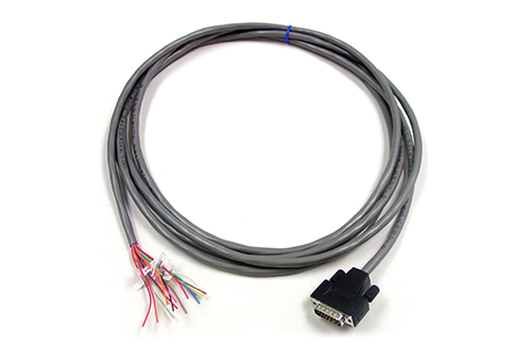
RS485 Communication Module: Pinout, Cable and Wiring

본문

Alternatively, the if the SPI interrupts are enabled, the SPI interrupt handler determines what caused the interrupt by reading the SPSR register to see which of the three status bits is set. Once the data has been exchanged, a flag bit in the SPSR status register is set to indicate that the transfer is complete. Consult the data sheets for any peripheral devices that you are interfacing to the SPI and, if a different configuration is needed, follow the instructions below to set up the appropriate SPI data transfer protocol. The only difference between the master and slave devices is that the master initiates the transmission. If the /SS pin of the master is an input and if a low input level is detected, the processor sets the MODF bit in the SPI status register a "mode fault" condition. The SPE bit turns on the SPI system. This function properly configures the directions of the SPI I/O pins, and configures the data transfer such that data is valid on the falling trailing edge of the clock, with the clock idling in the low state. SPIE is a local interrupt mask that allows an interrupt to be recognized when an SPI data transfer has completed, or if a write collision or mode fault is detected.
These steps greatly reduce the chance that the communicating devices might be damaged by contention on the SPI bus. In general, all devices on a network should use the same phase, polarity, and baud rate clock signal. Although the devices would share the same network, communications would only be understandable by members of the same group. Slave devices use the master in/slave out pin, MISO, for transmitting, and the master out/slave in pin, MOSI, for receiving data. Configured as a master device, the QScreen transmits bytes via the "master out/slave in" pin, MOSI. Given a properly wired network and a properly configured SPCR control register, a master device may transmit a message by simply storing the byte to the SPDR data register. The SPIF is set when a data transfer is complete, and is cleared by a read of the SPSR status register, followed by a read or write to the SPDR data register.
If SPIF is set, reading the received data or initiating a new data transfer automatically clears the SPIF bit. Setting the MSTR bit initializes the QScreen as a master, and clearing the MSTR bit initializes it as a slave. Any required SPI output signals must be configured as outputs, either by calling InitSPI() or by setting the appropriate bits in the Port D data direction register DDRD. Designed to be used with the SenseCAP Sensor Hub, this splitter is able to "split" one MODBUS RS485 port into 4. The RS485 splitter has one male interface that connects to the Sensor Hub and four female interfaces that link to the sensors. SenseCAP is a wireless sensing platform developed specifically for Industrial IoT, with applications in smart agriculture, smart cities, and other environmental sensing scenarios. The issue also exists in programmable logic controller applications. A mode fault occurs when the SPI senses that a multimaster conflict (MC68HC11F1 Technical Data Manual, p.8-7) exists on the network as explained above in connection with the /SS input. A write collision occurs when a byte is written to the SPI data register, SPDR, while data is being exchanged. The data transfer that is in process when the write collision occurs is completed.
After a data transfer is initiated by writing to the SPDR data register, the processor may poll the SPSR status register until the SPIF flag is set. This setting is only relevant for the master device, as it is the master’s clock which drives the transfer. Setting SPE (SPI enable) to 1 turns on the SPI system. The next section describes the registers that configure and control the QScreen Controller’s SPI. There are a variety of ways the MOSI, MISO, SCK and /SS pins on your QScreen Controller can be connected. Without termination resistors, signal reflections off the unterminated end of the cable can cause data corruption. When using the RS485 interface, for a specific transmission line, the maximum cable length allowed for data signal transmission from the RS485 interface to the load is inversely proportional to the baud rate of the signal transmission. RS-485, like RS-422, what is rs485 cable can be made full-duplex by using four wires.

댓글목록0
댓글 포인트 안내